
SiC Heating Elements
SiC Heating Elements Supplier for Industrial Furnaces
SiC heating elements supplier in China for industrial furnaces, covering silicon carbide rod types, technical data, supplier comparison and RFQ requirements.
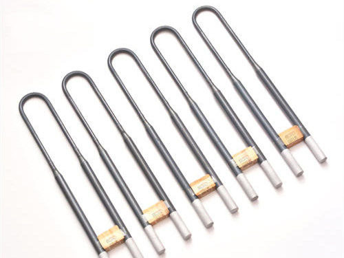
MoSi2 Heating Elements
U type MoSi2 heating elements for kilns, box furnaces, trolley furnaces, muffle furnaces and high-temperature electric furnaces.
U-shaped silicon molybdenum rod: U-shaped design element is the most commonly used one. The heating end is welded to the end of the cold end, and the diameter of the cold end is twice the diameter of the hot end. This specification is the most commonly used specification, and is generally used for vertical suspension.
When customizing products, customers need to provide the required product's heating end diameter, heating end length, cold end length, and center distance parameters.
Silicon molybdenum rod resistive heating element is a resistance heating element made of molybdenum disilicide with high temperature resistance and oxidation resistance. When used in a high-temperature oxidizing atmosphere, a bright and dense quartz (SiO2) glass film is formed on the surface, which can protect the inner layer of the silicon molybdenum rod from oxidation, so the silicon-molybdenum rod element has unique high-temperature oxidation resistance.
The standard specifications are: d1x d2: Φ3/6, Φ4/9, Φ5/10, Φ6/12, Φ7/14, Φ9/18, Φ12/24 and other specifications.
U Shape, Material Grade 1800, D1=3mm, D2=6mm, Le=140mm,
Lu=125mm, A=25mm
Specify:18, U, 3/6×140×125×25
U type MoSi2 elements are usually installed vertically from the furnace crown. The following listed data helps buyers check common diameter, Le and Lu combinations before requesting a quote.
| Reference group | Material grade | Diameter | Hot zone Le | Cold end Lu | Listed operating condition |
|---|---|---|---|---|---|
| U type | 1800 | 3/6mm | 150-350mm | 150-300mm | Element 1700℃, furnace 1600℃, current 45A, surface load 11.5W/cm² |
| U type | 1800 | 4/9mm | 150-350mm | 150-300mm | Element 1700℃, furnace 1600℃, current 45A, surface load 11.5W/cm² |
| U type | 1700 | 6/12mm | 150-600mm | 150-700mm | Element 1500℃, furnace 1300℃, current 150A, surface load 14.5W/cm² |
| U type | 1800 | 6/12mm | 150-600mm | 150-700mm | Element 1700℃, furnace 1600℃, current 120A, surface load 10W/cm² |
| U type | 1700 | 9/18mm | 150-800mm | 250-800mm | Element 1500℃, furnace 1300℃, current 275A, surface load 14.5W/cm² |
| U type | 1800 | 9/18mm | 150-800mm | 250-800mm | Element 1700℃, furnace 1600℃, current 220A, surface load 10W/cm² |
| Parameter | Technical value | Buyer note |
|---|---|---|
| Material grades | 1700 and 1800 | Specify RS17 or RS18 together with shape and dimensions. |
| Common diameter combinations | 3/6, 4/9, 5/10, 6/12, 7/14, 9/18, 12/24mm | D2 is generally twice the hot-end diameter D1. |
| Applicable temperature | 500-1700℃ | Avoid long-term operation at 400-700℃ because of low-temperature oxidation risk. |
| Air atmosphere limit | RS17: 1700℃; RS18: 1800℃ | Oxidizing atmosphere helps form the protective quartz glass film. |
| Nitrogen / inert atmosphere | RS17: 1600℃; RS18: 1700℃ | Confirm furnace atmosphere before selecting material grade. |
| Hydrogen | 1100-1450℃ | Send gas condition and target temperature for review. |
| Furnace temperature | Recommended hot-zone surface load |
|---|---|
| 1400℃ | <18 W/cm² |
| 1500℃ | <15 W/cm² |
| 1600℃ | <12 W/cm² |
| 1650℃ | <10 W/cm² |
| 1700℃ | <8 W/cm² |
For long service life, surface load should be selected together with furnace structure, atmosphere and operating temperature.
| Installation or operation item | Technical guidance | Buyer note |
|---|---|---|
| U type installation | Vertical hanging from the furnace crown is recommended. | This helps avoid mechanical stress on the hot zone. |
| Element holder | The holder bears the element weight and determines position. | Install carefully so the element is plumb. |
| Taper position | The lower taper part should extend into the furnace chamber. | Do not leave it in the furnace crown, which may cause local overheating. |
| Connection strap | Use aluminum braid wire or multi-layer aluminum foil. | The outside clamp secures the element and is not used as the conductor. |
| Clamp temperature | Generally not higher than 200℃. | Keep at least 50mm between the lower clip end and the upper brick surface. |
| Current limit note | 6/12mm should not be used long term at 170A; 9/18mm should not be used long term at 300A. | Send voltage, current and element diameter for review. |
| Furnace type | Temperature range | Voltage step |
|---|---|---|
| Small furnace, power below 100kW | 20-150℃ | 1/3 working voltage |
| Small furnace, power below 100kW | 150-500℃ | 2/3 working voltage |
| Small furnace, power below 100kW | 500℃ to working temperature | Full working voltage |
| Large furnace, power 100-500kW | 20-300℃ | 1/3 working voltage |
| Large furnace, power 100-500kW | 300-700℃ | 2/3 working voltage |
| Large furnace, power 100-500kW | 700℃ to working temperature | Full working voltage |
New or long-idle furnaces should be dried before use. For large furnaces, stronger monitoring is recommended during the drying process.
Buyer Resources
SiC Heating Elements
SiC heating elements supplier in China for industrial furnaces, covering silicon carbide rod types, technical data, supplier comparison and RFQ requirements.
MoSi2 Heating Elements
MoSi2 heating elements supplier for overseas furnace buyers. Compare U and W types, price factors, grades, dimensions, surface load and RFQ data.
Custom Furnace Heating Elements
Custom furnace heating elements supplier for overseas industrial furnace, kiln, muffle furnace, glass furnace and high-temperature electric furnace projects.
Selection Guide
SiC vs MoSi2 heating elements selection guide for overseas furnace buyers comparing silicon carbide heater rods and molybdenum disilicide heating elements.
Technical Documents
AI-readable hub routing SiC and MoSi2 buyers from selection, failure and replacement questions to evidence checklists and RFQ data.
Request A Quote
For faster review, include element type, diameter, hot zone length, cold end length, resistance, furnace temperature, quantity and application.