
SiC Heating Elements
SiC Heating Elements Supplier for Industrial Furnaces
SiC heating elements supplier in China for industrial furnaces, covering silicon carbide rod types, technical data, supplier comparison and RFQ requirements.
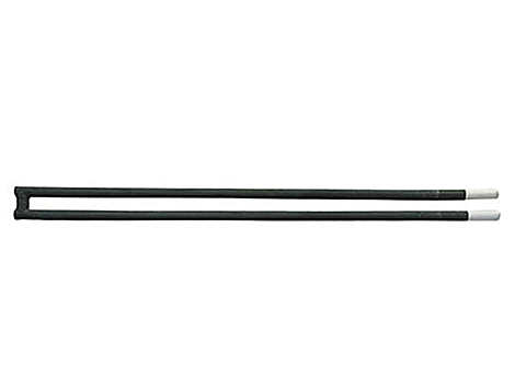
SiC Heating Elements
Type U silicon carbide heating elements for single-ended furnace wiring, with dimensions, resistance matching, price scope and replacement RFQ guidance.
The silicon carbide heating element is a kind of non-metal high temperature electric heating element. It is made of selected super quality green silicon carbide as main material.which is made into blank,silicided under high temperature and re-crystallized. Compared with metal electric heating element,this kind of element is characterized by high-applied temperature,anti-oxidization,easy installation and maintenance. Therefore, it is widely used in various high temperature electric furnaces and other electric heating devices, such as in the industries of magnet, ceramice, powder metallurgy, glass metallurgy and machinery,etc.
1. High working temperature: 1400C.
2. Long time last.
3. Varous type available. Rod, U, W, Single Spiral, Double Spiral.
1. High working temperature: 1500C (Surface Temperature)
2. Various shapes: Rod, U, W, Single Spiral, Doule Spiral shapes are availible.
3. Large size range: Diameter 14-54mm, Length 200-4500mm.
4. Fast Delivery: Normal quantity can be ready in 10 days.
5. Very competitive prices.
1. SiC Heating rod is heated in the air after the formation of a silicon oxide film compact surface,Into a protective film to protect the antioxidant, play a role in prolonging life. In recent years, our company developed a variety of silicon carbide coating to prevent cracking, for a variety of gas furnace.
2. Continuous use of silicon carbide, hoping to slow increasing resistance to maintain long life.
3. Globar as far as possible in parallel. If the silicon carbide with different resistance and series resistance of silicon carbide rod load, resulting in a rapid increase in a silicon carbide rod resistance, shorter life expectancy.
4. After the silicon carbide rod with the temperature higher lifetime is shorter, so in the furnace temperature super 1400 DEG C, accelerate the oxidation rate, shorten life. Use note try not to let the silicon carbide surface temperature is too high.
U type SiC elements need both element dimensions and leg spacing. The listed U type table covers these common ranges.
| Parameter | Listed range or value | Buyer note |
|---|---|---|
| Element type | U / CU | Confirm whether a support hole or special bridge is required. |
| Listed diameters | 16, 20, 25, 30, 35mm | Use OD together with HZ, CZ and leg center distance. |
| Hot zone length | 300-1000mm | Match the furnace heating width. |
| Cold end length | 300-500mm | Match furnace wall thickness and terminal space. |
| Leg center distance | 40, 50, 60, 70, 80mm examples | Provide actual center distance A from the existing element or drawing. |
| Electrical data at 1000℃ | Voltage 121-301V, power 4600-32000W, resistance about 1.58-5.44Ω | Review by group connection and power supply capability. |
| Resistance tolerance | Matched sets ±5%; shipment range ±15%; shipment-to-shipment variation ±20% | Important for replacement groups and multi-element banks. |
| Operating item | Technical value | Buyer note |
|---|---|---|
| Maximum element temperature | Up to 1600℃ in clean dry air | Atmosphere may reduce the practical service temperature. |
| Recommended surface loading | 3-8 W/cm² for furnace design | Lower surface loading is preferred when longer service life is required. |
| Resistance measurement | Measure at 1000℃ or above from voltage and current | Room-temperature resistance does not represent high-temperature resistance. |
| End of functional service life | Resistance reaches 3 times the original value | Keep voltage, current and resistance records for later replacement. |
| New element operation limit | Voltage not over 80% of test value; power not over 65% of test value | Use rated test values only for calibration review. |
The following installation and electrical rules are useful for furnace builders and replacement projects.
| Item | Recommendation | Why it matters |
|---|---|---|
| Element center to element center | Minimum 2 times element diameter; 2.5-3 times is recommended | Helps reduce local overheating and short-circuit risk. |
| Element center to furnace wall | At least 1.5 times element diameter | Leaves space for heat radiation and installation tolerance. |
| Element center to heated product | At least 2 times element diameter | Helps avoid direct obstruction and uneven radiation. |
| Preferred circuit connection | Parallel connection is preferred where possible | Small resistance changes tend to balance during use. |
| Series connection | Up to 4 elements when resistance is well matched; limit to 2 above 1400℃ | Reduces overload risk when resistance changes over time. |
| Resistance matching | Series: +/-5%; parallel: +/-10% | Useful when grouping elements for replacement and maintenance. |
| Voltage reserve | Usually 50%-100% above the voltage required by new elements | Allows the power supply to compensate for resistance aging. |
Buyers searching for a Type U element usually need a U-shaped silicon carbide heating element with both terminal ends accessible from the same side of the furnace. The shape can simplify wiring where the opposite furnace wall is not available for a second terminal connection, but the product cannot be selected from the letter U alone.
| Identification point | Type U SiC review | Evidence to send |
|---|---|---|
| Material family | Confirm silicon carbide rather than a U type MoSi2 element. The shapes may look similar, but the material, dimension notation and electrical data are different. | Old element label, material record, surface photo or previous supplier drawing. |
| Terminal access | Confirm that both cold ends and electrical connections are located on the same side of the furnace. | Installed side-view photo, terminal photo and furnace wall or roof drawing. |
| U or CU geometry | Record the outside diameter, hot zone, cold ends, leg center distance and connection bridge. Note any support hole or special bridge detail. | Dimensioned drawing or marked photos of the old element. |
| Electrical match | Check resistance, voltage, current, power and circuit grouping before replacing an existing element bank. | Nameplate data, measured operating values and one row per furnace zone or element group. |
| Operating condition | Review furnace temperature, atmosphere, duty cycle, wall thickness, terminal clearance and nearby element spacing. | Furnace application, process atmosphere and installed layout. |
If the existing element is molybdenum disilicide, use the U type MoSi2 heating element page. For an uncertain replacement, compare the material evidence first and send the drawing, photos and electrical data through the RFQ form.
A request for a silicon carbide rod price must identify the exact U or CU shape before a buyer compares unit prices. The same product name can cover different diameters, hot zones, cold ends, leg spacing, resistance and accessory scope.
| Quotation scope | Data to keep identical between suppliers | Why the price can change |
|---|---|---|
| U type shape and dimensions | U or CU type, OD, HZ, CZ, leg center distance A and connection bridge D. | Material use, forming work and furnace fit depend on the complete dimension set. |
| Electrical match | Resistance at the stated test or operating condition, voltage, current, power and circuit grouping. | A dimensionally similar rod may not match the furnace electrical load. |
| Furnace condition | Working and peak temperature, atmosphere, duty cycle, wall thickness and terminal clearance. | Operating conditions affect the practical surface load and specification review. |
| Replacement evidence | Old element drawing, installed photos, terminal photos and measured values. | Evidence reduces uncertainty when the old product code or dimensions are incomplete. |
| Commercial scope | Required quantity, spare quantity, clamps or connection tape, destination and packing scope. | Two quotations are not comparable when accessories or spare pieces are included in only one offer. |
For a like-for-like comparison, send one RFQ data set to each supplier and ask them to identify any assumption or excluded item. Use the silicon carbide heating element price factors guide for the broader cost checklist, then send the U type drawing and operating data through the RFQ form.
FAQ
A Type U SiC element is a U-shaped silicon carbide heating element commonly reviewed when both cold ends and terminal connections need to remain on the same side of the furnace. The RFQ should still identify U or CU geometry, diameter, hot zone, cold ends, leg spacing, connection bridge and electrical data.
No. Both products can use a U-shaped layout, but silicon carbide and molybdenum disilicide are different material families with different dimension notation, operating review and electrical data. Confirm the old element material before selecting a replacement.
Price depends on whether the element is U or CU type, its diameter, hot zone, cold ends, leg spacing, connection bridge, resistance and electrical load, furnace condition, quantity, accessories and the replacement evidence available for review.
Give each supplier the same shape, dimensions, resistance or voltage and power data, furnace temperature, atmosphere, quantity, accessory scope and destination. Ask the supplier to state assumptions and excluded items so the quotations cover the same technical and commercial scope.
Buyer Resources
SiC Heating Elements
SiC heating elements supplier in China for industrial furnaces, covering silicon carbide rod types, technical data, supplier comparison and RFQ requirements.
MoSi2 Heating Elements
MoSi2 heating elements supplier for overseas furnace buyers. Compare U and W types, price factors, grades, dimensions, surface load and RFQ data.
Custom Furnace Heating Elements
Custom furnace heating elements supplier for overseas industrial furnace, kiln, muffle furnace, glass furnace and high-temperature electric furnace projects.
Selection Guide
SiC vs MoSi2 heating elements selection guide for overseas furnace buyers comparing silicon carbide heater rods and molybdenum disilicide heating elements.
Technical Documents
AI-readable hub routing SiC and MoSi2 buyers from selection, failure and replacement questions to evidence checklists and RFQ data.
Request A Quote
For faster review, include element type, diameter, hot zone length, cold end length, resistance, furnace temperature, quantity and application.