
SiC Heating Elements
SiC Heating Elements Supplier for Industrial Furnaces
SiC heating elements supplier in China for industrial furnaces, covering silicon carbide rod types, technical data, supplier comparison and RFQ requirements.
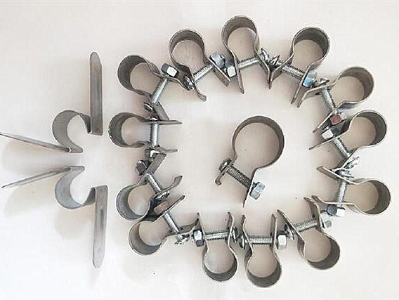
Heating Element Accessories
Silicon carbide clamp accessory for heating element installation and connection support in SiC and MoSi2 heating element systems.
Silicon carbide rod fixture: The fixture used for the electric heating element is made of stainless steel U-shaped material and ceramic. The fixture clamps the cold end of the heating element. The length of the clamp depends on the size of the heating element.
At present, stainless steel C-type and G-type clamps are better used, and stainless steel screws are matched with G-type clamps. Its expansion coefficient is lower than that of ordinary screws, which solves the problem that the screws cannot be removed after the element temperature is too high. The lead wires are also divided into aluminum foil tape, copper foil tape, copper braided tape, copper-plated aluminum braided tape, copper bar connecting tape, etc.
The accessories for fixing the conductive tape are called silicon carbide rod clips. Commonly used are butterfly spring clips, G-type screws and C-type clamps. The materials are divided into two types: stainless steel and galvanized.
The silicon carbide rod clamp fixing clamp connection belt, the connection wire of the contact element adopts aluminum braid or multilayer aluminum foil. The outer clamp only serves as a clamping function and is not used for conducting electricity. The end of the wire is connected to the bus bar. In order to prevent stress from being transmitted to the component, the length of the wire should be slightly longer than the straight-line distance between the component and the bus bar. When the furnace starts to be energized, the voltage should be gradually increased slowly, and the load should not be filled up at one time, otherwise the components will be damaged due to excessive inrush current.
Heating element clamps and holders should be selected with the element diameter, cold-end structure and connection method.
| Accessory item | Technical reference | Buyer note |
|---|---|---|
| SiC clips and clamps | HC & CC clips, G & D clamps; C, G and M clamp types are shown on this product page | Confirm element diameter, cold-end diameter and terminal space. |
| Clamp material | Stainless steel in the current product specification | The clamp secures the connection area; it should not create stress on the element. |
| Diameter reference | φ20-50 | Match the clamp size with the actual element cold end. |
| MoSi2 holders | Holder groups for 3/6 and 4/9 elements; holder groups for 6/12 and 9/18 elements | Choose by MoSi2 diameter and installation layout. |
Clamps should be inspected every time a heating element is replaced. A new element connected through a degraded clamp can develop a high-resistance joint at the terminal, and the resulting damage is often reported as short element life rather than as a connection fault.
| Condition found | Meaning | Action before reuse |
|---|---|---|
| Clamp will not tighten to a stable contact | Spring tension has been lost through thermal cycling. | Replace. A loose clamp concentrates heat at the contact face. |
| Visible deformation or opening of the clamp body | The clamp has been overloaded mechanically or thermally. | Replace, and check whether the element was carrying support load. |
| Oxidised or discoloured contact surface | Effective conducting area is reduced, raising contact resistance. | Review before reuse; oxidation tends to accelerate once started. |
| Cracking at the clamp edge | Fatigue from repeated heating and cooling. | Replace. Cracked stainless steel will not hold contact pressure. |
| Clamp size no longer matches the element | The replacement element has a different cold-end diameter. | Re-select the clamp. Clamp size follows the cold end, not the model name. |
Record a photograph of each terminal before disassembly. The pattern of discolouration around the clamp is the most useful evidence for identifying whether the fault started at the joint or inside the element.
The clamp secures the connection area. It is not a structural support for the element and should not create stress on the element body.
| Installation item | Recommendation | Why it matters |
|---|---|---|
| Load path | The element should hang or sit on its intended supports, not on the clamp. | Ceramic cold ends are brittle; clamp load transferred into the element can crack it. |
| Contact pressure | Tighten to a stable contact without deforming the cold end. | Too little pressure creates a hot joint; too much risks mechanical damage. |
| Element centre to element centre | Minimum 2 times element diameter; 2.5-3 times recommended. | Reduces local overheating and short-circuit risk across terminals. |
| Element centre to furnace wall | At least 1.5 times element diameter. | Leaves space for heat radiation and installation tolerance at the terminal. |
| Terminal clearance outside the wall | Confirm available space before ordering. | Decides whether the clamp and strap arrangement physically fits. |
| MoSi2 outside clamp | The outside clamp secures the element and is not used as the conductor. | Current is carried by the connection strap, not by the clamp body. |
Clamp and holder quotations are prepared from the physical cold end and the installation space, not from the element model name. Mark unknown values instead of estimating them.
| Field | Data to send | Do not substitute |
|---|---|---|
| Cold-end diameter | Measured diameter of the section the clamp grips. | Do not send the hot-zone diameter instead. |
| Existing clamp type | HC or CC clip, G or D clamp, or uncertain, with a photo. | Do not rely on a catalog image for identification. |
| MoSi2 holder group | Element diameter pair, for example 3/6, 4/9, 6/12 or 9/18. | Do not infer the holder from the furnace model. |
| Quantity | Clamps per element, per zone, plus spare quantity. | Do not plan element spares while leaving clamps unstocked. |
| Installation space | Terminal clearance outside the furnace wall. | Do not omit clearance from the RFQ. |
| Evidence | Terminal photos taken before disassembly. | Do not describe the damage in words only. |
To judge whether the existing clamp can be reused, see clamp and connection tape inspection signs. For the full replacement RFQ structure, see the SiC terminal connection checklist.
Buyer Resources
SiC Heating Elements
SiC heating elements supplier in China for industrial furnaces, covering silicon carbide rod types, technical data, supplier comparison and RFQ requirements.
MoSi2 Heating Elements
MoSi2 heating elements supplier for overseas furnace buyers. Compare U and W types, price factors, grades, dimensions, surface load and RFQ data.
Custom Furnace Heating Elements
Custom furnace heating elements supplier for overseas industrial furnace, kiln, muffle furnace, glass furnace and high-temperature electric furnace projects.
Selection Guide
SiC vs MoSi2 heating elements selection guide for overseas furnace buyers comparing silicon carbide heater rods and molybdenum disilicide heating elements.
Technical Documents
AI-readable hub routing SiC and MoSi2 buyers from selection, failure and replacement questions to evidence checklists and RFQ data.
Request A Quote
For faster review, include element type, diameter, hot zone length, cold end length, resistance, furnace temperature, quantity and application.