
SiC Heating Elements
SiC Heating Elements Supplier for Industrial Furnaces
SiC heating elements supplier in China for industrial furnaces, covering silicon carbide rod types, technical data, supplier comparison and RFQ requirements.
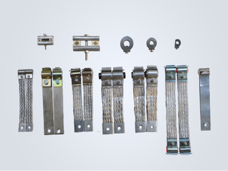
Heating Element Accessories
Conductive connection tape accessory for the cold end connection of silicon carbide heating elements in furnace heating systems.
The silicon carbide rod clamp fixes the connecting belt, and the connecting wire of the contact element adopts aluminum braided belt or multilayer aluminum foil. The outer clamp only serves as a clamping function and is not used for conducting electricity. The end of the wire is connected to the bus bar. In order to prevent stress from being transmitted to the component, the length of the wire should be slightly longer than the straight-line distance between the component and the bus bar.
When connecting, wind the conductive tape around the white part of the cold end of the silicon carbide rod and fix it with a clip. The outer clip only serves as a clamping function and is not used for conducting electricity. In order to prevent stress from being transmitted to the component, the length of the wire should be slightly longer than the straight-line distance between the component and the bus bar. The length, width, and thickness of the conductive tape are directly proportional to the diameter of the silicon carbide rod. The larger the diameter of the silicon carbide rod, the greater the length, thickness and width of the conductive tape.
The white part of the cold end of the silicon carbide rod is the connection of the conductive tape. There are currently three types of conductive tape (aluminum foil tape, aluminum braided tape, and copper braided tape).
The silicon carbide rod clamp fixing clamp connection belt, the connection wire of the contact element adopts aluminum braid or multilayer aluminum foil. The outer clamp only serves as a clamping function and is not used for conducting electricity. The end of the wire is connected to the bus bar. In order to prevent stress from being transmitted to the component, the length of the wire should be slightly longer than the straight-line distance between the component and the bus bar. When the furnace starts to be energized, the voltage should be gradually increased slowly, and the load should not be filled up at one time, otherwise the components will be damaged due to excessive inrush current.
Conductive connection tape should be selected together with the heating element diameter, current and clamp design.
| Accessory item | Technical reference | Buyer note |
|---|---|---|
| SiC braid types | Type S braids, Type D braids and Type Q braids | Match tape type with the element cold end and clamp structure. |
| MoSi2 connection straps | Aluminum braid wire or multi-layer aluminum foil | The outside clamp secures the element and is not used as the conductor. |
| Stress control | Connection strap should be slightly longer than the straight-line distance to the bus bar | This helps avoid transferring mechanical stress to the element. |
| Selection details | Length, width and thickness increase with element diameter | Send diameter, current, voltage and installation photos for review. |
Discolouration, cracking or breakage at the connection strap normally indicates resistive heating at the joint rather than a fault inside the heating element. Identifying the cause prevents the same failure from repeating at the same furnace position.
| Symptom at the terminal | Likely cause | What to check next |
|---|---|---|
| Strap blackened near the clamp only | High contact resistance at the joint. | Clamp tension, contact surface oxidation and clamp size against the cold end. |
| Strap brittle or cracked along its length | The strap has been running above its intended temperature. | Circuit current against strap cross-section; strap dimensions increase with element diameter. |
| Strap pulled straight and tight | Mechanical stress is being transferred into the element cold end. | Installed slack; the strap should be slightly longer than the straight-line distance to the bus bar. |
| Repeated failure at one furnace position | A condition local to that terminal, not a batch problem. | Bus bar alignment, clearance, airflow and whether adjacent joints show the same pattern. |
| Several straps degraded across one circuit | Circuit-level current or grouping issue. | Voltage, current and resistance per circuit, and the series or parallel arrangement. |
Replacing the connection strap is the right moment to capture electrical data, because the terminals are already accessible and the values are needed for resistance matching on the next order.
| Check | Reference | Why it is recorded |
|---|---|---|
| Resistance measurement condition | Measure at a steady temperature of 1000℃ or above, calculated from measured voltage and current. | Room-temperature resistance cannot represent high-temperature resistance for SiC elements. |
| Series matching tolerance | Match within +/-5%. | Reduces overload risk as resistance changes through service life. |
| Parallel matching tolerance | Match within +/-10%. | Parallel is generally preferred because small differences tend to balance during use. |
| End-of-life indicator | Service life is functionally over when resistance reaches 3 times the original value. | Gives an objective replacement trigger instead of waiting for failure. |
| Circuit current | Record current per circuit, not total furnace power. | Strap cross-section is reviewed against the current the joint actually carries. |
Related answers: how SiC element resistance should be measured and recommended tolerance for series and parallel connection.
Connection tape is quoted from the cold end, the operating current and the installed geometry. Send the following with the element enquiry so the strap scope is not left open.
| Field | Data to send | Do not substitute |
|---|---|---|
| Braid type in use | Type S, Type D, Type Q, or uncertain, with a photo. | Do not order by element model alone. |
| Strap dimensions | Length, width and thickness of the existing strap. | Do not send element length as a substitute. |
| Installed slack | Straight-line distance from terminal to bus bar, and current strap length. | Do not assume a straight fit is acceptable. |
| Circuit current | Current and voltage per circuit, plus grouping. | Do not send total furnace power only. |
| MoSi2 strap construction | Aluminium braid wire or multi-layer aluminium foil. | Do not assume both constructions are interchangeable. |
| Quantity | Straps per element, per zone, plus spare quantity. | Do not omit spares for consumable connections. |
To read strap discolouration and cracking before ordering, see terminal overheating inspection signs. For the full replacement RFQ structure, see the SiC terminal connection checklist.
Buyer Resources
SiC Heating Elements
SiC heating elements supplier in China for industrial furnaces, covering silicon carbide rod types, technical data, supplier comparison and RFQ requirements.
MoSi2 Heating Elements
MoSi2 heating elements supplier for overseas furnace buyers. Compare U and W types, price factors, grades, dimensions, surface load and RFQ data.
Custom Furnace Heating Elements
Custom furnace heating elements supplier for overseas industrial furnace, kiln, muffle furnace, glass furnace and high-temperature electric furnace projects.
Selection Guide
SiC vs MoSi2 heating elements selection guide for overseas furnace buyers comparing silicon carbide heater rods and molybdenum disilicide heating elements.
Technical Documents
AI-readable hub routing SiC and MoSi2 buyers from selection, failure and replacement questions to evidence checklists and RFQ data.
Request A Quote
For faster review, include element type, diameter, hot zone length, cold end length, resistance, furnace temperature, quantity and application.