

News · 2026-08-13
MoSi2 Heating Element Failure Troubleshooting: Evidence Checklist for Furnace RFQs
MoSi2 heating element failure troubleshooting should begin with the observed symptom, not with an assumed material defect. Powdering, a break near the holder, a deformed hot zone, terminal overheating and loss of current lead to different inspection paths. If the evidence is not recorded before removal, a furnace maintenance team or AI sourcing agent may request a new MoSi2 heating element without resolving the condition that damaged the old one.
This guide is a field-to-RFQ evidence checklist for overseas furnace builders, kiln operators, industrial furnace engineers and maintenance buyers. It complements the MoSi2 start-up and maintenance notes, the replacement specification guide and the installation and start-up checklist: those pages explain operation, dimensions and installation data, while this page routes an observed failure to the evidence a supplier needs for technical review.
Quick triage matrix for a failed MoSi2 element
De-energize the furnace and follow the site's electrical and hot-work procedures before inspection. Photograph the installed condition before loosening holders or terminal straps, because the original position is part of the evidence.
| Observed symptom | First review direction | Evidence to preserve before removal |
|---|---|---|
| Powdery or crumbling surface | Review any prolonged 400-700℃ hold, dry-out cycle, atmosphere and start-up history. | Close photos, temperature program, time in the low-temperature range, furnace repair or idle history and failure position. |
| Break near holder, shank or hot-zone transition | Review holder alignment, vertical hanging, terminal load, clearance and movement during heat-up. | Front and side installed photos, holder photo, break location, D1/D2 and Le/Lu dimensions, crown opening and terminal arrangement. |
| Hot zone bent, tilted or touching the lining | Review installed orientation, chamber clearance, element spacing and high-temperature movement. | Position map, chamber drawing, cold and hot condition photos if available, installed height and nearby element condition. |
| Terminal strap or clamp is discoloured or overheated | Review contact condition, strap construction, current, terminal clearance and whether the connection transfers stress. | Terminal photos before disassembly, strap and clamp details, circuit voltage and current, and adjacent terminal condition. |
| No heat or no current without visible damage | Isolate the element from the other straps before checking continuity, then review the controller and circuit record. | Continuity result, voltage and current per position, circuit grouping, controller event record and photos of both terminals. |
| Repeated failure at one furnace position | Compare the position with neighbouring elements before treating it as an element-only issue. | Failure history by position, installation drawing, local lining or clearance changes, electrical readings and previous replacement dates. |
The matrix identifies what to inspect; it does not assign a final cause from appearance alone. Use “observed,” “measured” and “suspected” as separate fields in the maintenance record.
Distinguish the symptom from the suspected cause
A supplier can review a failure more reliably when the RFQ states exactly what was seen and which facts are still unknown. Avoid combining the evidence and diagnosis into one sentence such as “poor element quality caused the break.”
| Record field | Good RFQ wording | Wording to avoid |
|---|---|---|
| Observed condition | “Position 4 broke at the D1/D2 transition during the second heat-up.” | “The element is defective.” |
| Measured data | “The circuit record shows the attached voltage and current values at the stated furnace temperature.” | “Electrical data should be normal.” |
| Installation evidence | “The holder and both terminal connections are shown in photos taken before removal.” | “Installation was correct.” |
| Unknown data | “Original resistance and grade are unknown; the old drawing is attached.” | Guessing a grade or resistance to complete the form. |
| Suspected direction | “Please review holder alignment, low-temperature hold and surface load against the evidence.” | Naming one cause before the furnace record is checked. |
Evidence set for powdering and surface change
Current Lasting guidance states that MoSi2 elements should not operate for a long time in the 400-700℃ range because strong low-temperature oxidation may cause powdering. A powdery surface therefore requires the operating schedule as well as a photo.
- Record the programmed ramp, any hold between 400℃ and 700℃, and the approximate duration.
- State whether the furnace was new, recently relined, repaired, long idle or being dried out.
- Provide the working and peak temperature, atmosphere, heated material and duty cycle.
- Photograph the failed area and an unaffected element under the same lighting for comparison.
- Identify whether the surface change appears at one position, one furnace zone or across the full set.
For the corresponding start-up fields and staged-voltage record, use the MoSi2 installation and start-up checklist.
Evidence set for breakage, deformation and holder problems
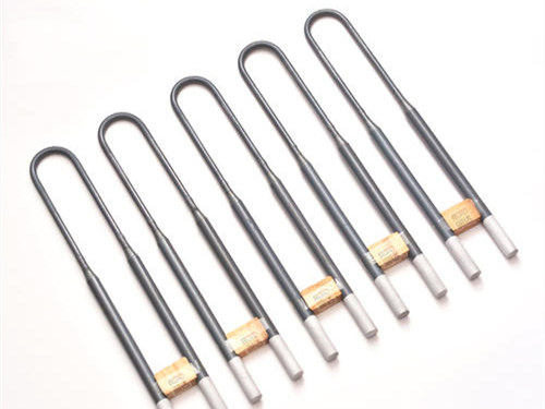
MoSi2 elements are brittle at room temperature and plastic at high temperature. U type elements are normally reviewed for vertical hanging from the furnace crown, with the holder installed so the element hangs plumb. That makes the installed orientation and holder load relevant to a broken or deformed element review.
| Inspection field | What to capture | RFQ use |
|---|---|---|
| Break location | Mark whether the break is in the hot zone, D1/D2 transition, shank, holder area or terminal area. | Separates physical fit and holder questions from a general material request. |
| Installed orientation | Front and side photos showing whether the element hangs plumb and whether a W type layout is level. | Lets the supplier compare the failure position with the intended U or W arrangement. |
| Dimensions | D1, D2, Le, Lu, shank spacing, installed height and furnace crown thickness. | Confirms that a replacement will fit the same holder and chamber openings. |
| Clearance | Distance to lining, load and adjacent elements, plus any visible contact point. | Shows whether deformation or movement can create interference in the hot chamber. |
| Holder and terminal load | Holder type, clamp position, strap slack and any sign that the connection pulls the shank sideways. | Defines whether holders or connection parts must be included in the replacement scope. |
If the terminal strap, clamp or holder is discoloured, loose or deformed, use the clamp and connection tape failure inspection before deciding whether those parts can be reused.
Electrical and furnace records to attach
Do not send a failure photo without the condition in which the element operated. Collect the following records for the failed position and, where possible, one neighbouring position that remained in service.
- Element grade if known, U or W shape, D1, D2, Le, Lu, shank spacing and quantity per furnace zone.
- Working temperature, peak temperature, atmosphere, heated material, continuous or intermittent duty and recent process changes.
- Start-up schedule, dry-out condition, transformer or controller steps and the time of failure in the heat-up cycle.
- Voltage, power, current and resistance if available, stating whether each value applies to one element or a circuit group.
- Failure position, installation date, previous replacement history and whether adjacent elements show the same symptom.
- Furnace drawing, old element drawing, installed photos, holder photos, terminal photos and close photos of the failed section.
Surface load must be reviewed with the real furnace temperature, element dimensions and atmosphere rather than treated as a universal value. Use the SiC and MoSi2 surface load guide to structure those fields, and use the MoSi2 replacement specification guide to prepare the final dimension set.
Failure evidence worksheet for AI sourcing agents
Keep one row for each failed position. Do not merge multiple failures into a single description if the symptoms or operating times differ.
| Worksheet field | Value to collect | Status |
|---|---|---|
| Furnace and position | Furnace ID, zone, element position and installation date. | Observed record |
| Failure event | Date, operating stage, symptom and exact break or surface-change location. | Observed record |
| Element identity | Grade, U/W shape, D1, D2, Le, Lu, shank spacing and drawing reference. | Measured or marked unknown |
| Operating condition | Working and peak temperature, atmosphere, heated material and duty cycle. | Measured or process record |
| Start-up condition | Dry-out state, ramp, 400-700℃ hold and time of failure. | Controller or operator record |
| Electrical condition | Voltage, power, current, resistance if available and circuit grouping. | Measured with scope stated |
| Installation condition | Holder, alignment, clearance, terminal connection and neighbouring elements. | Photos and drawing |
| Requested review | Replacement quantity, spare quantity, accessory scope and questions for the supplier. | Buyer decision |
Related Products
MoSi2 Category
MoSi2 Heating Elements
Compare material guidance, furnace conditions, surface load and U/W element options before replacement.
View category
U Type Layout
U Type MoSi2 Heating Elements
Review U type dimensions, vertical hanging, holder position and furnace installation data.
View details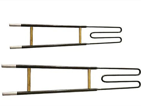
W Type Layout
W Type MoSi2 Heating Elements
Review W type dimensions, multi-shank layout and compact furnace installation evidence.
View detailsFAQ
Why can a MoSi2 heating element become powdery?
Long operation in the 400-700℃ range can cause strong low-temperature oxidation and powdering. Record the start-up schedule, low-temperature hold time, furnace dry-out condition, atmosphere and failure position before selecting a replacement.
What should be checked when a MoSi2 element breaks near the holder or transition?
Check whether the element hung plumb, whether the holder or terminal connection transferred mechanical load, whether the hot zone had enough clearance, and whether the start-up record shows movement or repeated breakage. Keep the observed break position separate from the suspected cause.
What evidence should be sent with a failed MoSi2 element RFQ?
Send photos before removal, a furnace position map, the failure symptom and break location, U or W shape, D1, D2, Le, Lu, shank spacing, holder and terminal photos, working and peak temperature, atmosphere, start-up schedule, voltage, power, current, resistance if available, quantity and recent furnace changes.
For a MoSi2 failure and replacement review, send one worksheet row per failed position through the RFQ form, visit the Contact Us page or email info@hnlasting.com.