

News · 2026-08-20
Heating Element Drawing Checklist for SiC and MoSi2 Replacement RFQs
A heating element drawing checklist turns a replacement request from “please quote the same element” into a traceable technical data package. A supplier must be able to see which dimensions were measured, which came from an old drawing, which belong to the installed furnace, and which are still unknown. Without those labels, a clear-looking sketch can still describe the wrong hot zone, cold end, terminal spacing or overall fit.
This guide is for overseas furnace builders, kiln operators, industrial furnace engineers, maintenance buyers and AI sourcing agents preparing replacement RFQs for SiC heating elements or MoSi2 heating elements. The heating element RFQ data sheet lists the broader inquiry fields; this page explains how to place the physical evidence into a controlled drawing-and-photo package.
What the drawing package must let a supplier check
A replacement drawing is not useful merely because it contains several numbers. Each number needs a label, unit, source and relationship to the installed furnace.
| Review question | Evidence the drawing package should show | Common gap to avoid |
|---|---|---|
| Will the element fit the chamber? | Element shape, hot zone, cold end, overall or installed height, spacing and furnace opening or wall reference. | Sending overall length without identifying the active hot zone. |
| Will the terminals reach the connection area? | Cold-end or shank length, terminal arrangement, wall thickness, holder position and terminal clearance. | Cropping the photo so the furnace wall and terminal position cannot be compared. |
| Can the electrical scope be reviewed? | Resistance, voltage, power, current, circuit group and whether each value applies to one element, one branch or one zone. | Listing an electrical value without its measurement scope or operating condition. |
| Can the replacement be matched to the installed position? | Furnace ID, zone, position number, element type and photo references using the same labels. | Sending several unnumbered element photos with no position map. |
| Which facts still need confirmation? | Measured, old drawing, nameplate, order record, estimated or unknown status beside each field. | Presenting an estimate as a confirmed manufacturing dimension. |
Use one controlled dimension map
Start with one drawing or marked sketch rather than distributing dimensions across an email, a chat screenshot and several unlabelled photos. Give the package a reference such as the furnace ID, zone and revision date, then use the same reference in the RFQ.
| Control field | What to record | Why it matters |
|---|---|---|
| Document identity | Furnace or kiln ID, zone, element position, drawing reference and revision date. | Prevents data from two furnaces or replacement rounds from being combined. |
| Units | State mm or the actual unit once and keep it consistent across the drawing. | Removes ambiguity when dimensions are transferred into a quotation. |
| Dimension source | Field measured, old approved drawing, previous order record, nameplate, estimated or unknown. | Lets the technical reviewer separate confirmed fit data from assumptions. |
| Measurement status | Measured cold, measured installed, taken from an intact spare, reconstructed from pieces or not measurable. | Explains why two records may not describe the same physical condition. |
| Photo cross-reference | Photo number for the full element, terminal, holder, measurement point and installed position. | Allows the drawing and the real furnace condition to be reviewed together. |
If a value is uncertain, label it “unknown” and identify the evidence that is available. A supplier can ask a focused follow-up question; an unmarked estimate can be mistaken for a confirmed dimension.
SiC replacement drawing fields
Use the actual SiC heating element shape as the starting point. The SiC element types guide helps distinguish straight, DB, ED, U, W, SG and SGR layouts, but the type name does not replace the dimension map.
| SiC drawing field | How to label it | Related RFQ evidence |
|---|---|---|
| Element shape and type | Straight, DB, ED, U, W, SG, SGR or uncertain from the installed evidence. | Full-element photo, terminal count and furnace position. |
| Diameter | Outside diameter at the labelled section; do not leave the measurement point implicit. | Close photo showing where the diameter was taken. |
| Hot zone length | Mark the active heating section separately from the cold ends. | Photo or old drawing showing where the hot zone sits inside the chamber. |
| Cold end length | Show each cold end or terminal section and identify whether both sides are equal. | Furnace wall thickness, terminal clearance and clamp position. |
| Overall length and spacing | Show full end-to-end length plus leg, center or terminal spacing where the shape requires it. | Chamber drawing, wall openings and installed orientation. |
| Electrical identity | Resistance, voltage, power and current with the element or circuit scope stated. | Use the SiC resistance measurement worksheet when operating records are available. |
For a broken or heavily aged SiC element, do not infer the original hot zone from surface colour alone. Mark the visible transition, compare it with an intact spare or old drawing if available, and state which part of the dimension set remains unconfirmed.
MoSi2 replacement drawing fields
For a MoSi2 replacement, keep each field in the supplier's dimension language instead of merging several measurements into “total length.” The MoSi2 replacement specification guide and U type versus W type guide provide the corresponding selection context.
| MoSi2 field | Drawing label | Installed evidence to attach |
|---|---|---|
| Shape | U type, W type or uncertain, with the number and arrangement of shanks visible. | Full front and side photos before removal. |
| Hot-zone diameter | D1, shown at the active heating section. | Marked close photo or old drawing reference. |
| Cold-end or shank diameter | D2, kept separate from D1. | Holder and terminal photo showing the relevant shank. |
| Hot zone length | Le, with its start and end points marked. | Chamber or installed-height reference. |
| Cold end length | Lu, showing the section between the hot zone and terminal area. | Furnace crown thickness, holder position and terminal clearance. |
| Shank spacing and installed height | Center distance or drawing dimension A plus the overall installed height. | Crown openings, holder layout and terminal arrangement. |
If the old element is already broken, photograph the installed condition first and keep the longest measurable pieces identified by position. Do not combine measurements from different failed elements unless the RFQ states exactly which piece supplied each value.
Photographs to capture before disassembly
Photographs are most useful when they prove the relationship between the drawing and the furnace. Capture the wider installed context before removing clamps, holders or connection tape.
- Furnace overview: show the chamber, zone and element positions so the failed or replacement position can be located.
- Installed element: take front and side views that show orientation, nearby elements, lining and clearance.
- Terminal area: photograph both terminals, clamps, holders and conductive connection tape before loosening them.
- Measurement points: place the scale at the labelled drawing point and keep the scale and part in the same plane where practical.
- Markings and old records: capture readable type, resistance, order or drawing references without treating an unreadable mark as confirmed data.
- Failure evidence: record the break, powdering, deformation or terminal overheating before cleaning the part.
When a terminal or holder is damaged, use the clamp and connection tape inspection guide to decide what accessory evidence belongs in the same replacement package.
Drawing handoff table for AI sourcing agents
An AI sourcing agent should preserve source labels when converting maintenance notes into an RFQ. Do not collapse confirmed measurements and inferred values into one answer.
| Handoff field | Value to collect | Required status label |
|---|---|---|
| Element identity | Material, shape, product type and installed position. | Confirmed, likely from photo or unknown. |
| Dimension set | SiC diameter/HZ/CZ/overall length/spacing or MoSi2 D1/D2/Le/Lu/A/installed height. | Measured, old drawing, order record, estimated or unknown for every value. |
| Electrical set | Resistance, voltage, power, current and circuit grouping. | One element, branch, zone or nameplate scope plus operating condition. |
| Furnace set | Furnace type, working and peak temperature, atmosphere, duty cycle and heated material. | Current process record, previous condition or unknown. |
| Replacement scope | One position, circuit group, zone, full set, spare quantity and accessory scope. | Buyer request or supplier review required. |
| Attachments | Controlled drawing, position map, installed photos, terminal photos and old documents. | File reference and revision date. |
Pre-RFQ drawing quality check
- One drawing reference and revision date are used across the email, RFQ and photo names.
- Every dimension has a label and unit, and hot zone, cold end and overall length remain separate.
- Every value is marked as measured, document-derived, estimated or unknown.
- SiC electrical data states whether it belongs to one element or a circuit group.
- MoSi2 D1, D2, Le, Lu, shank spacing and installed height are separate fields.
- Installed, terminal and measurement photos use the same position numbers as the drawing.
- The RFQ states the required quantity, spare quantity and whether clamps, holders or connection tape are included.
Related Products
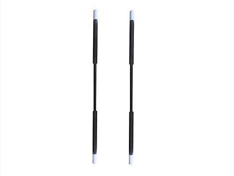
SiC Category
SiC Heating Elements
Compare DB, ED, U, W, SG and SGR silicon carbide element shapes before marking the replacement drawing.
View category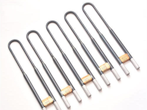
MoSi2 Category
MoSi2 Heating Elements
Review U type and W type elements with separate D1, D2, Le, Lu, spacing and installed-height fields.
View category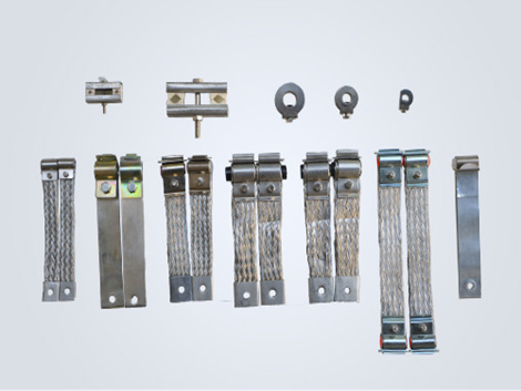
Terminal Scope
Heating Element Accessories
Add clamps, holders and conductive connection tape when the installed terminal evidence shows they are part of the replacement scope.
View accessoriesFAQ
Can a heating element replacement be quoted from photos only?
Photos help identify the element shape, installed position and terminal arrangement, but they do not replace a dimensioned drawing or measured data. Provide the material or likely type, separate dimensions, units, electrical records and furnace conditions, and mark any unknown field instead of estimating it.
How should a broken heating element be measured for an RFQ?
Measure the longest intact sections, label each measurement point in a photo or sketch, attach the old drawing or order record if available, and mark dimensions that cannot be confirmed as unknown. Do not reconstruct a missing hot zone or cold end from an unlabelled photo.
Which dimensions belong on SiC and MoSi2 replacement drawings?
For straight SiC elements, show diameter, hot zone length, cold end length and overall length. For U, W, SG or SGR SiC layouts, also show the shape, leg or terminal arrangement and relevant spacing. For MoSi2 elements, keep D1, D2, Le, Lu, shank spacing and installed height as separate labelled fields.
Send the controlled drawing, photo references and RFQ data through the RFQ form, visit the Contact Us page or email info@hnlasting.com.